



Flex-Series™ Install

Install guides and advice for your ObsidianWire Flex-Series® harness
  • Easy. Not Instant.

    For a secure connection, take your time, and follow directions carefully.

Install Info:

Below you will find:

  • Wiring Diagrams
  • Install Instructions
  • Links to More Help

Compatibility

  • A Complete System

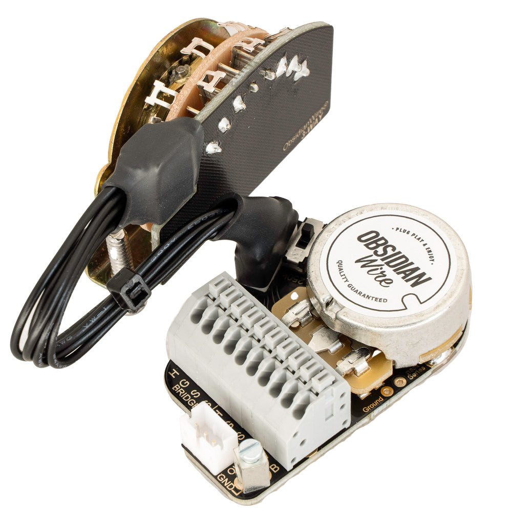
    Made to work with compatible Flex-Series™ parts

    The ObsidianWire Flex-Series™ is a complete wiring system made to work with other compatible Flex-Series™ parts. This will not work with parts that do not belong to a compatible Flex-Series™ system.

    • Volume Controls
    • Tone Controls
    • Switches
    • Accessories
    • Pro-Wired Jacks
  • Obsidianwire harness being installed in a Les Paul with colored wires showing

    Pickups

    Designed to work with most standard pickups. Special pickup wires are not required.

    • Single Coils - Use 250k Volume
    • Humbuckers -Use 500k Volume
    • P90s - Use 500k Volume

    Does NOT suit Active / Battery powered pickups

    Note - Vintage braided pickup wires such as those found on vintage and re-production humbuckers are not a good match for the solder-less connectors on some Flex-Series products.

  • Pot Shaft Length & Size

    • Short Shaft: Pickguard / Control Plate Mount Only
    • Long Shaft: Rear / Cavity Mount Only
      - Standard Long Shaft: Min Body Thickness 33mm
      - Push / Pull Long Shaft: Min Body Thickness 45mm
    • Hole Size: 9.54mm

    Ream smaller 'Metric' holes to 9.54mm

  • Knobs

    Compatible with US spec split, or solid shaft knobs

    • Split Shaft - 24 Spline
    • Solid 1/4" - Knobs with included shaft adapter / brass bushing

    Not Compatible with smaller 'Metric' size knobs

Will It Fit?

Layout Guide:

Flexible - Not Universal

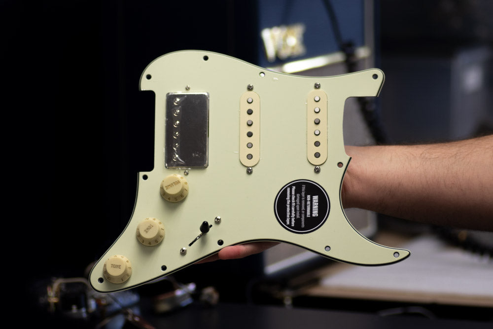
The Flex-Series is a versatile range of guitar wiring designed to accommodate a variety of guitars with different hole layouts.

Please refer to the product information for details on which guitar types each product is designed to fit.

Wiring Diagrams:

Match your wiring diagram to your Pro-Wired Electronics model.

Check carefully.

Notes:

  • Slot 1 - Always Closest to Jack
  • Spare ground wires go to screw down connector
  • Ground all metal parts including tremolo / bridge and cavity sheilding

  • M1 | One Pickup Wiring

    1. H - Pickup Hot
    2. G - Pickup Ground
    3. S1 - Pickup Series
    4. S2 - Pickup Series
    5. W - Output White
    6. B - Output Ground

    • KILL SWITCH - Insert wires two wires from kill switch. One slot per wire.
    • All other ground wires to screw down ground connector - GND

    Note: Two wire pickups - Leave 'SERIES' slots empty

    Pickup Wire Colour Info
  • M2-S | Two Pickup // S-Type

    1. H - Bridge Pickup Hot
    2. G - Bridge Pickup Ground
    3. S1 - Bridge Pickup Series
    4. S2 - Bridge Pickup Series
    5. H - Neck Pickup Hot
    6. G - Neck Pickup Ground
    7. S1 - Neck Pickup Series
    8. S2 - Neck Pickup Series
    9. W - Output White
    10. B - Output Ground

    • All other ground wires to screw down ground connector - GND

    Note: Two wire pickups - Leave 'SERIES' slots empty

    Pickup Wire Colour Info

Install Instructions:

  • A man removing the pickguard from a black fender stratocaster.

    1) Prepare your space & set aside some time

    • A clean install is a good install
    • Take your time, and be precise
    • Wiring parts can be fragile. Be gentle.

    You will need

    • Wire cutters
    • Fine tip flat head screw driver
    • Phillips head screw driver for switch screws
    • Crescent or socket for potentiometer nuts
  • 2) Remove Your Old Wiring Harness

    • Cut the pickup, and ground wires from your old harness, and remove it from your bass.
    • Cut as close to the old harness as possible to maintain the length of your wires.
    • Remove the harness from your pickguard
  • 3) Mount your new Wiring harness

    • Use the hardware provided to install your new harness
    • DO NOT remove the nuts that come pre-loaded on your harness. These act as a spacer between your harness and the pickguard

  •  

    4) Find Your Wiring Diagram

    • Find the correct diagram for your Strat® & Harness above.
    • Ensure the diagram is the correct one for the harness you are installing.
    Download Manual
  •  

    5) Identify Your Pickup Wires

    • For most pickups:
      Hot = White
      Ground = Black
    • For different pickups you can check our pickup wire guide below, or check with the manufacturers install manual

    Pickup Color Codes
  • 6) Prepare Your Wires

    • Take your time & be precise
    • Strip pickup and ground wire insulation leaving 6mm (1/4”) of bare wire.
    • Twist loose strands of wire between your fingers to create a firm tip.
    • Cleanly prepared wires are essential for a good connection

  •  

    7) Press & Hold Connector Button

    • Use a fine screw driver to press and hold the connector button above the wire slot.
    • This opens an internal clamp so the wire can be inserted to the slot.
    • For a full guide on using the solder-less connectors, check below
    Connector Guide
  • 8) Insert Wire & Release Button

    • Insert the wire at a 45° angle.
    • Insert all of the exposed section of wire (6mm or 1/4")
    • Release the button and the wire should hold firmly.
    • Test the wire by giving it a gentle pull before moving on to the next wire.
    • Your solderless connector is made to fit a range of wire sizes, from standard Fender cloth wire down to tiny Seymour Duncan style wires
  • 9) Install knobs & Switch Tip

    • Use The correct size knobs & tips
    • Use Only US spec / imperial knobs (24 spline or spline-less)
    • Take time to align the knob splines
    • Press gently
    • Support the pot base as you press on the knob
    • Never force a tight knob, as this can damage the pot
  • 10) Mount your pickguard & String up for testing

    • Be careful to ensure that all wires are neatly tucked in to the cavity
    • Ensure that the switch and jack does not connect with the cavity wall as this can cause the signal to round out
    • Ensure that there is enough clearance at the bottom of the cavity, so the switch does not ground out on the cavity floor

More Help?